VMD是一款非常强大的分子动力学后处理软件,而在使用中有个问题经常困扰新手,如何在周期性模型上加上晶胞格子使其看起来更“漂亮”一点呢?VMD默认是不画晶格的
但作为一个强大的软件,能实现这个功能是肯定的,现在就有两种方法可以在VMD软件中画出晶格,试试吧:
(1)VMD内置的pbctool工具箱,可直接在vmd控制台或者Tk控制台(Main menu->Extensions->Tk Console)中输入以下命令:
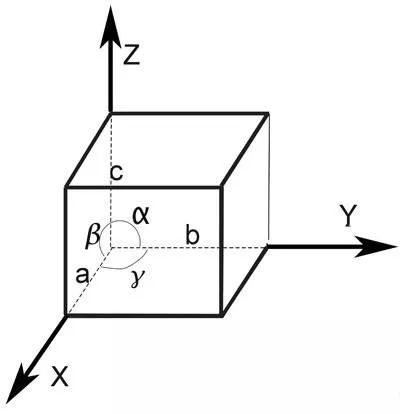
pbc set [list a b c alpha beta gamma]
pbc box -on
其中,a、b、c、alpha、beta、gamma是各个晶胞参数,如下图所示:

还可以设置box的线型、线宽和颜色,分别通过以下命令:
pbc box -style lines|dashed|
pbc box -width 2
pbc box -color red
更多选项可查阅:
http://www.ks.uiuc.edu/Research/vmd/plugins/pbctools/
(2)tcl脚本:vmd_draw_unitcell。将下面内容保存在名为vmd_draw_unitcell.tcl的文件,放在vmd安装目录下(如:C:Program FilesUniversity of IllinoisVMD)
# vmd extension procedure:
# provide a ‘draw unitcell’ command
#
# $Id: vmd_draw_unitcell.tcl,v 1.2 2005/01/11 13:05:12 akohlmey Exp $
# Time-stamp:
#
# Copyright (c) 2003-2005 by
# add a unitcell graphic to a molecule via a draw subcommand.
#
# options:
# cell (vmd|auto|[list ]), default: “vmd”
# “vmd” will use the internal values,
# “auto” will build an orthogonal unitcell from the result of
# ‘measure minmax’ plus 1 angstrom added in each direction.
# else a list of a,b,c,alpha,beta,gamma will be assumed.
# origin ([list ]|auto), default: {0.0 0.0 0.0}, “auto” with ‘cell auto’
# style: (lines|dashed|rod) default: line
# width: default: 1.0
# resolution: default: 8
#
proc vmd_draw_unitcell {molid args} {
# parse arguments
foreach {flag arg} $args {
switch $flag {
cell { set cell “$arg” }
origin { set origin “$arg” }
style { set style “$arg” }
width { set width “$arg” }
resolution { set resolution “$arg” }
default { puts “unknown option: $flag”; return }
}
}
if [info exists cell] {
if {![info exists origin] && $cell == “auto”} { set origin auto }
} else {
set cell vmd
}
if ![info exists origin] { set origin {0.0 0.0 0.0} }
if ![info exists style] { set style lines }
if ![info exists width] { set width 1 }
if ![info exists resolution] { set resolution 8 }
# FIXME: add some checks on the arguments here.
# handle auto keywords
if {$cell == “auto” || $origin == “auto” } {
set sel [atomselect $molid {all}]
set minmax [measure minmax $sel]
$sel delete
unset sel
if {$origin == “auto” } {set origin [vecsub [lindex $minmax 0] {1 1 1}]}
if {$cell == “auto”} {
set cell [vecadd [vecsub [lindex $minmax 1] [lindex $minmax 0]] {2 2 2}]
lappend cell 90.0 90.0 90.0
}
}
if {$cell == “vmd” } {set cell [molinfo $molid get {a b c alpha beta gamma}]}
global M_PI
set sa [expr sin([lindex $cell 3]/180.0*$M_PI)]
set ca [expr cos([lindex $cell 3]/180.0*$M_PI)]
set cb [expr cos([lindex $cell 4]/180.0*$M_PI)]
set cg [expr cos([lindex $cell 5]/180.0*$M_PI)]
set sg [expr sin([lindex $cell 5]/180.0*$M_PI)]
# set up cell vectors according to the VMD unitcell conventions.
# the a-vector is collinear with the x-axis and
# the b-vector is in the xy-plane.
set a [vecscale [lindex $cell 0] {1 0 0}]
set b [vecscale [lindex $cell 1] “$ca $sa 0”]
set c [vecscale [lindex $cell 2] “$cb [expr ($ca – $cb*$cg)/$sg] [expr sqrt((1.0 + 2.0*$ca*$cb*$cg – $ca*$ca – $cb*$cb – $cg*$cg)/(1.0 – $cg*$cg))]”]
# set up cell vertices
set vert(0) $origin
set vert(1) [vecadd $origin $a]
set vert(2) [vecadd $origin $b]
set vert(3) [vecadd $origin $a $b]
set vert(4) [vecadd $origin $c]
set vert(5) [vecadd $origin $a $c]
set vert(6) [vecadd $origin $b $c]
set vert(7) [vecadd $origin $a $b $c]
unset sa ca cb cg sg
set gid “”
switch $style {
rod {
# set size and radius of spheres and cylinders
set srad [expr $width * 0.003 * [veclength [vecadd $a $b $c]]]
set crad [expr 0.99 * $srad]
# draw spheres into the vertices …
for {set i 0} {$i < 8} {incr i} {
lappend gid [graphics $molid sphere $vert($i) radius $srad resolution $resolution]
}
# … and connect them with cylinders
foreach {i j} {0 1 0 2 0 4 1 5 2 3 4 6 1 3 2 6 4 5 7 3 7 5 7 6} {
lappend gid [graphics $molid cylinder $vert($i) $vert($j) radius $crad resolution $resolution]
}
}
lines {
set width [expr int($width + 0.5)]
foreach {i j} {0 1 0 2 0 4 1 5 2 3 4 6 1 3 2 6 4 5 7 3 7 5 7 6} {
lappend gid [graphics $molid line $vert($i) $vert($j) width $width style solid]
}
}
dashed {
set width [expr int($width + 0.5)]
foreach {i j} {0 1 0 2 0 4 1 5 2 3 4 6 1 3 2 6 4 5 7 3 7 5 7 6} {
lappend gid [graphics $molid line $vert($i) $vert($j) width $width style dashed]
}
}
default { puts “unknown unitcell style: $style” ; return }
}
# return list of graphics indices so that they can be saved and deleted later.
return $gid
}
############################################################
# Local Variables:
# mode: tcl
# time-stamp-format: “%u %02d.%02m.%y %02H:%02M:%02S %s”
# End:
############################################################
用记事本打开vmd安装目录下的vmd.rc文件,在最后添加一行:
source C:\Program Files (x86)\University of Illinois\VMD\vmd_draw_unitcell.tcl
然后在vmd控制台或这tk控制台即可输入一下命令显示晶胞格子:
draw unitcell cell [list a b c alpha beta gamma]
注意:a b c alpha beta gamma需要全部注明。
详细说明请看下面一段英文表述:
# cell (vmd|auto|[list ]), default: “vmd”
# “vmd” will use the internal values,
# “auto” will build an orthogonal unitcell from the result of
# ‘measure minmax’ plus 1 angstrom added in each direction.
# else a list of a,b,c,alpha,beta,gamma will be assumed.
# origin ([list ]|auto), default: {0.0 0.0 0.0}, “auto” with ‘cell auto’
# style: (lines|dashed|rod) default: line
# width: default: 1.0
# resolution: default: 8
本文转载自xianggui7895,转载目的在于知识分享,本文观点不代表V-suan云平台立场。
原创文章,作者:菜菜欧尼酱,如若转载,请注明来源华算科技,注明出处:https://www.v-suan.com/index.php/2023/12/01/ad9e647007/
